 Inside the Asset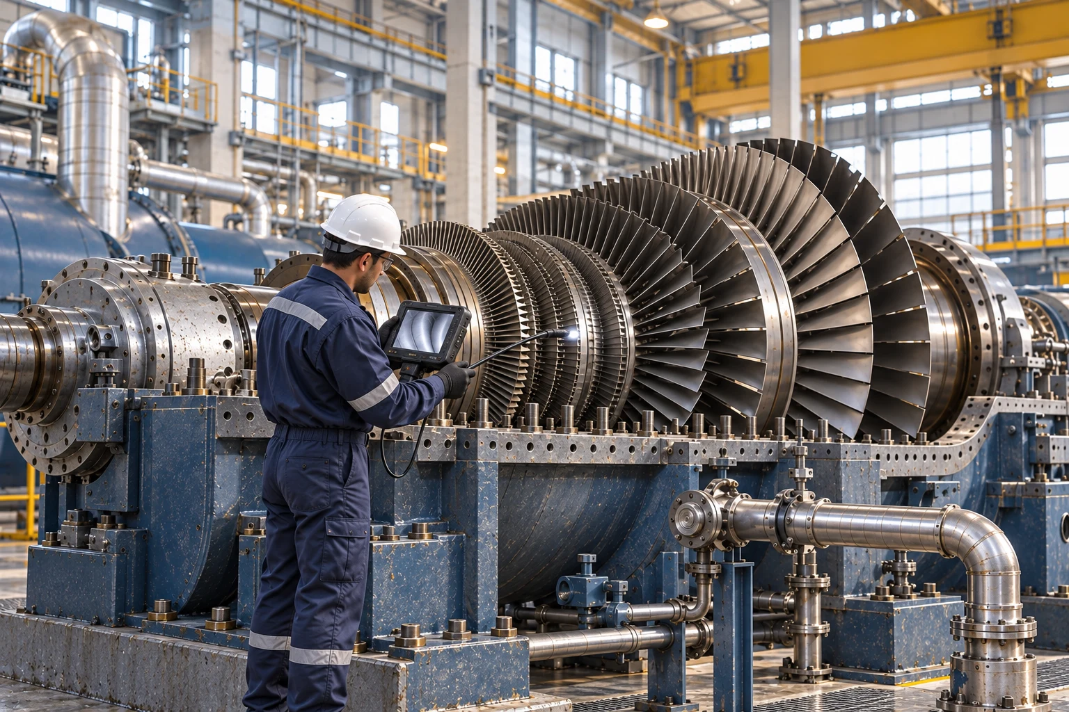
Videoscope inspection of reachable steam-turbine blade surfaces during a planned outage. AI-generated illustration; instrument appearance and geometry are illustrative.
What it is
A steam turbine converts energy in steam into shaft power. It can drive an electrical generator or industrial equipment such as a compressor or pump. The steam supply, exhaust arrangement and driven machine determine how it operates within the plant. [1]
This guide focuses on a conventional industrial turbine with an accessible casing and shaft train. Condensing, back-pressure and extraction machines differ; the illustration is a component-location reference, not a universal layout. The inspection scope must include support systems as well as the rotor.
How it works
Steam admission. Stop and control valves regulate steam entering the machine. The inlet arrangement belongs in the inspection plan because a rotor survey alone says nothing about valve response or protection performance. [1, 2]
Casing and steam path. Stationary passages direct steam through rotating blade rows, transferring energy to the shaft. Pressure, temperature and steam conditions change through the machine. Record the stage and viewing direction when localizing a finding. [1]
Rotor, bearings and coupling. Bearings support the rotating assembly; the coupling transmits power to the driven equipment. Shaft alignment, bearing condition and machine operating state provide context for vibration observations.
Seals and oil system. Shaft seals manage leakage at casing penetrations. The oil system supports bearings and, in some designs, control functions. Reservoirs, filters, pumps and cooling equipment are part of a complete route.

AI-generated component-location illustration, not to scale. Use the asset’s drawings and identifiers to localize findings; highlighted zones illustrate component areas and do not define complete examination coverage.
Where it fails
Blades and flow passages. Erosion, deposits, corrosion or mechanical damage can affect blade condition and performance. Accessible surfaces are only part of the scope: a clean borescope image does not establish the condition of every blade root or concealed region. [3]
Rotor and highly stressed regions. Suspected cracking needs an examination selected for material, geometry and crack location. OEM-specific rotor assessment may require access or tests beyond a routine visual survey. [3]
Casing, seals and valves. Leakage, rub evidence, distortion or degraded valve response warrant follow-up. Keep observations at joints and seals separate from functional checks of the admission and protection systems. [2]
Bearings and support systems. Changes in vibration, oil condition or bearing temperature may indicate a developing problem, but the symptom is not the diagnosis. Compare similar speed, load and thermal conditions before assigning a cause.
How it gets inspected
Build the route around the machine configuration, operating history, starts, trips and previous findings. Collect operating-condition evidence while the turbine is running, then define which internal examinations require a planned outage. Agree stage numbering, bearing IDs and the orientation used for photographs.
OEM inspection and overhaul scopes differ in how much of the machine is opened. Select the outage scope for the specific turbine and findings; a calendar interval or a remote camera survey should not be treated as a complete life assessment. [2, 3]
Equipment for the job
Choose the method for the question, then the instrument and configuration for the asset. The following options address different parts of the inspection.
Remote visual inspection. A suitable industrial videoscope, such as the Evident IPLEX GT used elsewhere in this series, can document reachable steam-path surfaces during an authorized outage. Match probe diameter, reach and viewing direction to the opening. Record hidden regions and inspection-port limitations.
Vibration and speed reference. Use suitable installed monitoring or a portable analyzer with the sensors and speed reference needed for the question. Compare spectra, waveforms or trends under known operating conditions. A single overall reading cannot independently separate imbalance, alignment, rubbing and other causes. [4]
Targeted nondestructive testing. Qualified specialists may use ultrasonic, magnetic-particle, penetrant or other examinations appropriate to the component and suspected damage. The turbine design and procedure determine preparation, access and interpretation; the method name alone does not establish adequate coverage. [3] An Olympus EPOCH 650 is one option for conventional ultrasonic examination when the component-specific procedure calls for it.
Oil and bearing assessment. Use a repeatable oil-sampling point and laboratory program, supported by bearing-temperature and operating records. Document recent oil changes, filtration work and sampling conditions. A satisfactory sample cannot clear every mechanical defect in the rotor train.
Thermal and visual rounds. A suitable thermal camera can help compare accessible surfaces, joints and auxiliary equipment. Emissivity, insulation and reflections affect interpretation. Thermal imaging does not see through the casing or establish internal blade condition. A FLIR T540 is an example for accessible surface-temperature comparisons.
Valve and protection checks. Coordinate functional testing with the owner and turbine specialists under the machine-specific procedure. Record the test scope and disposition separately from condition images. A visually sound valve or instrument does not prove that the protection chain will operate as intended. [2]
Field note
Keep operating observations, internal images and specialist test results attached to the same component map. State which evidence supports a maintenance recommendation and which regions remain unexamined.
Why it matters
A turbine can affect electrical output or an entire process train. Reliable inspection connects visible condition to operating behavior and planned maintenance, helping the owner define a justified outage scope instead of collecting isolated photographs.
Ask your inspection provider
Which stages, rotor regions, bearings and protection functions will you assess, and what additional work is needed to resolve the areas a routine inspection cannot examine?
Field card - record on every route
Identify. Turbine ID, configuration, driven machine, stage and bearing references, service history and previous findings.
Record. Operating state, speed/load, steam conditions, viewing direction, instrument configuration and image or data reference.
Confirm. Tie significant findings to the selected follow-up examination and the responsible technical reviewer.
Flag gaps. Unreachable stages, concealed roots, blocked ports, unavailable operating data and functions not tested.
Close the loop. Maintenance recommendation, disposition authority, responsible person and the record used for the next comparison.
Support for the inspection
Arrange an access review, suitable instruments and method-specific training before the outage. Coordinate rotor work, protection testing and repair decisions with qualified turbine specialists. MFE equipment support can assist with inspection-tool selection; it is not a substitute for OEM engineering.
Sources and equipment references
1. Siemens Energy - Industrial steam turbines
2. Siemens Energy - Inspection and overhaul scope
3. GE Vernova - Steam turbine field inspections
4. SKF - Condition monitoring systems
5. MFE - Evident IPLEX GT videoscope
Educational guide by Jason Acerbi, an executive at MFE Inspection Solutions. These guides do not replace asset-specific procedures or engineering assessment. Named instruments are examples, not a claim that MFE supplies every diagnostic service or stocks every configuration. Confirm suitability and availability for the planned task.